Elimizde M25P128 Flash entegresine bilgisayarın seri portu üzerinden veri yazmak ve okumak amacıyla
tasarlanmış Şekil-1’deki gibi bir kart olduğunu düşünelim. Bu ödevde Şekil-1’de gösterilen SPI Flash
okuma kartı için, bilgisayarın seri portu üzerinden gelen komut ile M25P128 SPI Flash entegresinden
okuma yapabilen bir FPGA tasarımı yapınız. (Yazma yok)
M25P128 Entegresinin veri sayfasını aşağıdaki adresten indirebilirsiniz.
https://www.micron.com/~/media/documents/products/data-sheet/nor-flash/serial-nor/m25p/m25p128.pdf
Bilgisayardan gelen 4 byte okuma komutu şu şekilde olacaktır: |AA + 24 bit address|
Bu komut seri arayüzden gönderildikten sonra okuma işlemi yapılacak ve tek bir byte UART arayüzü
üzerinden bilgisayara gönderilcektir.
a) Ön tasarımı akış diyagramı şu şekildedir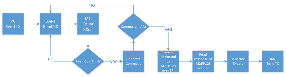
Bize ayrıca M25P128 entegresi gibi sinyal gönderecek bir modül gereklidir.
entity M25P128 is
    Port ( S : in STD_LOGIC;
           C : in STD_LOGIC;
           D : in STD_LOGIC;
           Q : out STD_LOGIC := 'Z');
end M25P128;

architecture Behavioral of M25P128 is
    signal counter : integer := 0;
    signal junkData : STD_LOGIC := '0';
begin

    process (C,S) begin
        if rising_edge(C) and S = '0' then
            if (counter < 32) then
                counter <= counter + 1;
            end if;
        end if;
        if falling_edge(C) and S = '0' then
            if (counter = 32) then
                junkData <= not(junkData);
                Q <= junkData;
            end if;
        end if;
        if (S = '1') then
            counter <= 0;
            Q <= 'Z';
        end if;
    end process;

end Behavioral;
Modül için testbench kodu
library IEEE;
use IEEE.STD_LOGIC_1164.ALL;

entity tb_M25P128 is
--  Port ( );
end tb_M25P128;

architecture Behavioral of tb_M25P128 is
    component M25P128 is
        Port ( S : in STD_LOGIC;
               C : in STD_LOGIC;
               D : in STD_LOGIC;
               Q : out STD_LOGIC);
    end component;
    signal S,C,D,Q : STD_LOGIC;
    constant period : time := 10ns;
begin
    MP : M25P128 port map(S => S,
               C => C,
               D => D,
               Q => Q);

    process begin
        S <= '1';
        D <= '0';
        wait for 3*period;
        S <= '0';
        wait for 50*period;
        S <= '1';
        wait for 10*period;
        S <= '0';
        wait;
    end process;

    process begin
        C <= '0';
        wait for period/2;
        C <= '1';
        wait for period/2;
    end process;

end Behavioral;
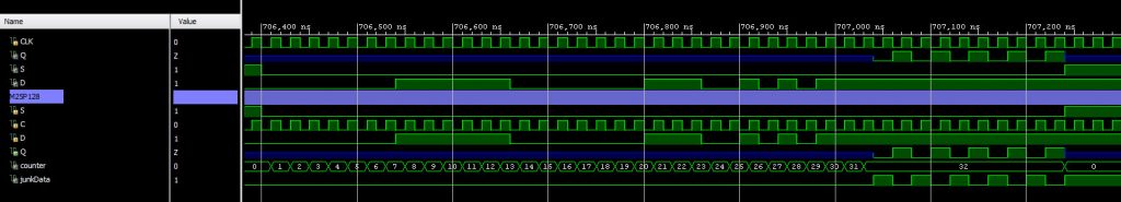
Simülasyon sonucu
b) UART arayüzü üzerinden haberleşme için gerekli kodu yazarak benzetimini yapalım.
-- Eric Bainville
-- Mar 2013

library IEEE;
use IEEE.STD_LOGIC_1164.ALL;
use IEEE.STD_LOGIC_UNSIGNED.ALL;
use IEEE.math_real.all;

entity uart is
  generic (
    DIVISOR: natural  -- DIVISOR = 100,000,000 / (16 x BAUD_RATE)
    -- 2400 -> 2604
    -- 9600 -> 651
    -- 115200 -> 54
    -- 1562500 -> 4
    -- 2083333 -> 3
  );
  port (
    clk: in std_logic;                         -- clock
    reset: in std_logic;                       -- reset

    -- Client interface
    rx_data: out std_logic_vector(7 downto 0); -- received byte
    rx_enable: out std_logic;                  -- validates received byte (1 system clock spike)
    tx_data: in std_logic_vector(7 downto 0);  -- byte to send
    tx_enable: in std_logic;                   -- validates byte to send if tx_ready is '1'
    tx_ready: out std_logic;                   -- if '1', we can send a new byte, otherwise we won't take it

    -- Physical interface
    rx: in std_logic;
    tx: out std_logic
  );
end uart;

architecture Behavioral of uart is
  constant COUNTER_BITS : natural := integer(ceil(log2(real(DIVISOR))));
  type fsm_state_t is (idle, active); -- common to both RX and TX FSM
  type rx_state_t is
  record
    fsm_state: fsm_state_t;                -- FSM state
    counter: std_logic_vector(3 downto 0); -- tick count
    bits: std_logic_vector(7 downto 0);    -- received bits
    nbits: std_logic_vector(3 downto 0);   -- number of received bits (includes start bit)
    enable: std_logic;                     -- signal we received a new byte
  end record;
  type tx_state_t is
  record
    fsm_state: fsm_state_t; -- FSM state
    counter: std_logic_vector(3 downto 0); -- tick count
    bits: std_logic_vector(8 downto 0); -- bits to emit, includes start bit
    nbits: std_logic_vector(3 downto 0); -- number of bits left to send
    ready: std_logic; -- signal we are accepting a new byte
  end record;

  signal rx_state,rx_state_next: rx_state_t;
  signal tx_state,tx_state_next: tx_state_t;
  signal sample: std_logic; -- 1 clk spike at 16x baud rate
  signal sample_counter: std_logic_vector(COUNTER_BITS-1 downto 0) := (others => '0'); -- should fit values in 0..DIVISOR-1

begin

  -- sample signal at 16x baud rate, 1 CLK spikes
  sample_process: process (clk,reset) is
  begin
    if reset = '1' then
      sample_counter <= (others => '0');
      sample <= '0';
    elsif rising_edge(clk) then
      if sample_counter = DIVISOR-1 then
        sample <= '1';
        sample_counter <= (others => '0');
      else
        sample <= '0';
        sample_counter <= sample_counter + 1;
      end if;
    end if;
  end process;

  -- RX, TX state registers update at each CLK, and RESET
  reg_process: process (clk,reset) is
  begin
    if reset = '1' then
      rx_state.fsm_state <= idle;
      rx_state.bits <= (others => '0');
      rx_state.nbits <= (others => '0');
      rx_state.enable <= '0';
      tx_state.fsm_state <= idle;
      tx_state.bits <= (others => '1');
      tx_state.nbits <= (others => '0');
      tx_state.ready <= '1';
    elsif rising_edge(clk) then
      rx_state <= rx_state_next;
      tx_state <= tx_state_next;
    end if;
  end process;

  -- RX FSM
  rx_process: process (rx_state,sample,rx) is
  begin
    case rx_state.fsm_state is

    when idle =>
      rx_state_next.counter <= (others => '0');
      rx_state_next.bits <= (others => '0');
      rx_state_next.nbits <= (others => '0');
      rx_state_next.enable <= '0';
      if rx = '0' then
        -- start a new byte
        rx_state_next.fsm_state <= active;
      else
        -- keep idle
        rx_state_next.fsm_state <= idle;
      end if;

    when active =>
      rx_state_next <= rx_state;
      if sample = '1' then
        if rx_state.counter = 8 then
          -- sample next RX bit (at the middle of the counter cycle)
          if rx_state.nbits = 9 then
            rx_state_next.fsm_state <= idle; -- back to idle state to wait for next start bit
            rx_state_next.enable <= rx; -- OK if stop bit is '1'
          else
            rx_state_next.bits <= rx & rx_state.bits(7 downto 1);
            rx_state_next.nbits <= rx_state.nbits + 1;
          end if;
        end if;
        rx_state_next.counter <= rx_state.counter + 1;
      end if;

    end case;
  end process;

  -- RX output
  rx_output: process (rx_state) is
  begin
    rx_enable <= rx_state.enable;
    rx_data <= rx_state.bits;
  end process;

  -- TX FSM
  tx_process: process (tx_state,sample,tx_enable,tx_data) is
  begin
    case tx_state.fsm_state is

    when idle =>
      if tx_enable = '1' then
        -- start a new bit
        tx_state_next.bits <= tx_data & '0';  -- data & start
        tx_state_next.nbits <= "0000" + 10; -- send 10 bits (includes '1' stop bit)
        tx_state_next.counter <= (others => '0');
        tx_state_next.fsm_state <= active;
        tx_state_next.ready <= '0';
      else
        -- keep idle
        tx_state_next.bits <= (others => '1');
        tx_state_next.nbits <= (others => '0');
        tx_state_next.counter <= (others => '0');
        tx_state_next.fsm_state <= idle;
        tx_state_next.ready <= '1';
      end if;

    when active =>
      tx_state_next <= tx_state;
      if sample = '1' then
        if tx_state.counter = 15 then
          -- send next bit
          if tx_state.nbits = 0 then
            -- turn idle
            tx_state_next.bits <= (others => '1');
            tx_state_next.nbits <= (others => '0');
            tx_state_next.counter <= (others => '0');
            tx_state_next.fsm_state <= idle;
            tx_state_next.ready <= '1';
          else
            tx_state_next.bits <= '1' & tx_state.bits(8 downto 1);
            tx_state_next.nbits <= tx_state.nbits - 1;
          end if;
        end if;
        tx_state_next.counter <= tx_state.counter + 1;
      end if;

    end case;
  end process;

  -- TX output
  tx_output: process (tx_state) is
  begin
    tx_ready <= tx_state.ready;
    tx <= tx_state.bits(0);
  end process;

end Behavioral;
UART için testbench kodu
library IEEE;
use IEEE.STD_LOGIC_1164.ALL;

entity tb_UART is
--  Port ( );
end tb_UART;

architecture Behavioral of tb_UART is
component uart is
generic (
  DIVISOR: natural
);
port (
  clk: in std_logic;   -- system clock
  reset: in std_logic;

  -- Client interface
  rx_data: out std_logic_vector(7 downto 0);  -- received byte
  rx_enable: out std_logic;  -- validates received byte (1 system clock spike)
  tx_data: in std_logic_vector(7 downto 0);  -- byte to send
  tx_enable: in std_logic;  -- validates byte to send if tx_ready is '1'
  tx_ready: out std_logic;  -- if '1', we can send a new byte, otherwise we won't take it

  -- Physical interface
  rx: in std_logic;
  tx: out std_logic
);
end component;
signal CLK, uartRST, RXen, TXen, TXrdy, RX, TX : STD_LOGIC;
signal RXdata, TXdata : STD_LOGIC_VECTOR(7 downto 0);
constant period : time := 10ns; -- 100 MHz
signal lowCLK : STD_LOGIC;
begin
    UART0 : uart
    generic map (DIVISOR => 54) -- 115200
    port map (
    clk => CLK, reset => uartRST,
    rx_data => RXdata, rx_enable => RXen,
    tx_data => TXdata, tx_enable => TXen, tx_ready => TXrdy,
    rx => RX,
    tx => TX
    );

    process begin
        CLK <= '0';
        wait for period/2;
        CLK <= '1';
        wait for period/2;
    end process;

    process begin
        lowCLK <= '0';
        wait for 864*period/2;
        lowCLK <= '1';
        wait for 864*period/2;
    end process;

    process begin
        uartRST <= '1';
        wait for 10*period;
        uartRST <= '0';
        wait;
    end process;

    process begin
        TXen <= '0';
        TXdata <= (others => '0');
        wait for 864*period;
        TXdata <= X"AA";
        TXen <= '1';
        wait for 1*period;
        TXdata <= X"00";
        TXen <= '0';
        wait until TXrdy = '1';
        TXdata <= X"FF";
        TXen <= '1';
        wait for 1*period;
        TXdata <= X"00";
        TXen <= '0';
        wait;
    end process;

    RX <= TX;

end Behavioral;
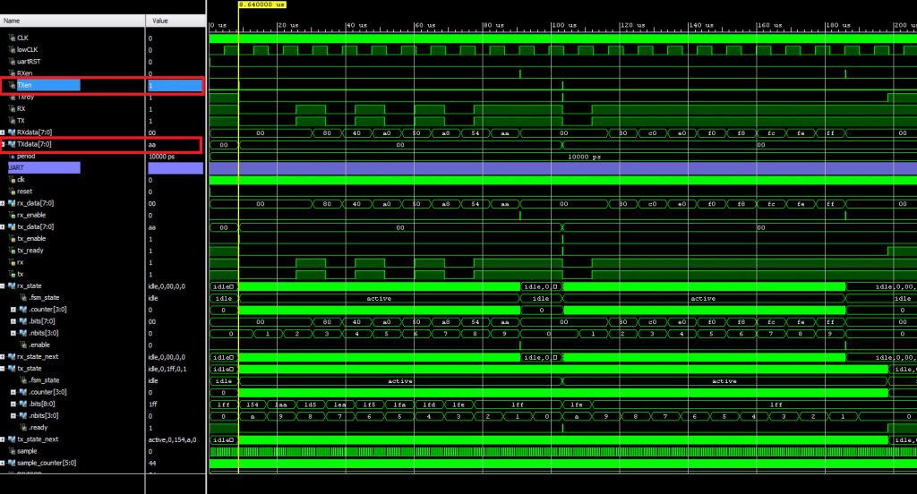
UART Modülü için benzetim sonuçları, burada TX sinyali devreye giriş olarak geri verildiği için RX sinyalinde de doğru oluştuğu gözlenebilmektedir.
c) M25P128 entegresini SPI arayüzü üzerinden okuyan ve diğer modülleri içeren ana modülü yazalım.
library IEEE;
use IEEE.STD_LOGIC_1164.ALL;
use IEEE.STD_LOGIC_UNSIGNED.ALL;

entity ZC0720FPGA is
    Port ( CLK : in STD_LOGIC;
           RX : in STD_LOGIC;
           TX : out STD_LOGIC := '0');
end ZC0720FPGA;

architecture Behavioral of ZC0720FPGA is
    component uart is
    generic (
      DIVISOR: natural
    );
    port (
      clk: in std_logic;   -- system clock
      reset: in std_logic;

      -- Client interface
      rx_data: out std_logic_vector(7 downto 0);  -- received byte
      rx_enable: out std_logic;  -- validates received byte (1 system clock spike)
      tx_data: in std_logic_vector(7 downto 0);  -- byte to send
      tx_enable: in std_logic;  -- validates byte to send if tx_ready is '1'
      tx_ready: out std_logic;  -- if '1', we can send a new byte, otherwise we won't take it

      -- Physical interface
      rx: in std_logic;
      tx: out std_logic
    );
    end component;
    component M25P128 is
        Port ( S : in STD_LOGIC;
               C : in STD_LOGIC;
               D : in STD_LOGIC;
               Q : out STD_LOGIC);
    end component;
    signal Dcounter : integer := 31;
    signal Qcounter : STD_LOGIC_VECTOR(4 downto 0) := (others => '0');
    signal data : STD_LOGIC_VECTOR(7 downto 0) := (others => '0');
    signal command : STD_LOGIC_VECTOR(31 downto 0) := (others => '0');
    signal commandReady : STD_LOGIC := '0';
    signal RXcounter : STD_LOGIC_VECTOR(3 downto 0) := (others => '0');
    type fsmState is (readRX, writeD, readQ, writeTX);
    signal fsmStatus, fsmNextStatus : fsmState;
    signal uartRST, RXen, TXen, TXrdy : STD_LOGIC := '0';
    signal RXdata, TXdata : STD_LOGIC_VECTOR(7 downto 0) := (others => '0');
    signal Q : STD_LOGIC;
    signal S, D : STD_LOGIC := '0';
begin

    UART0 : uart
    generic map (DIVISOR => 54) -- 50,000,000 / 115200 / 16
    port map (
        clk => CLK, reset => uartRST,
        rx_data => RXdata, rx_enable => RXen,
        tx_data => TXdata, tx_enable => TXen, tx_ready => TXrdy,
        rx => RX,
        tx => TX
        );

    MP : M25P128
    port map(S => S,
        C => CLK,
        D => D,
        Q => Q);

    process (fsmStatus) begin
        case fsmStatus is
            when readRX => S <= '1';
            when writeD => S <= '0';
            when readQ => S <= '0';
            when writeTX => S <= '1';
            when others => null;
        end case;
    end process;

    process (CLK) begin
        if falling_edge(CLK) then
            if fsmStatus = writeD then
                if (Dcounter > 0) then
                    D <= command(Dcounter);
                    Dcounter <= Dcounter - 1;
                elsif (Dcounter = 0) then
                    fsmNextStatus <= readQ;
                    Dcounter <= 31;
                end if;
            end if;
        elsif rising_edge(CLK) then
            if fsmStatus = readRX then
                TXen <= '0';
                commandReady <= '0';
                if RXen = '1' then
                    RXcounter <= RXcounter + '1';
                    command(31 downto 0) <= command(23 downto 0) & RXdata(0) & RXdata(1) & RXdata(2) & RXdata(3) & RXdata(4) & RXdata(5) & RXdata(6) & RXdata(7);
                end if;
                if (RXcounter = "0100") then
                    RXcounter <= "0000";
                    commandReady <= '1';
                end if;
                if (command(31 downto 24) = X"AA") and commandReady = '1' then
                    fsmNextStatus <= writeD;
                end if;
            end if;
            if fsmStatus = readQ then
                if (Qcounter < 8) then
                    TXdata(7 downto 0) <= TXdata(6 downto 0) & Q;
                    Qcounter <= Qcounter + 1;
                elsif (Qcounter = 8) then
                    fsmNextStatus <= writeTX;
                end if;
            end if;
            if fsmStatus = writeTX and TXrdy = '1' then
                TXen <= '1';
                fsmNextStatus <= readRX;
            end if;
        end if;
    end process;

    process (CLK) begin
        fsmStatus <= fsmNextStatus;
    end process;

end Behavioral;
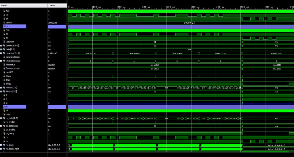
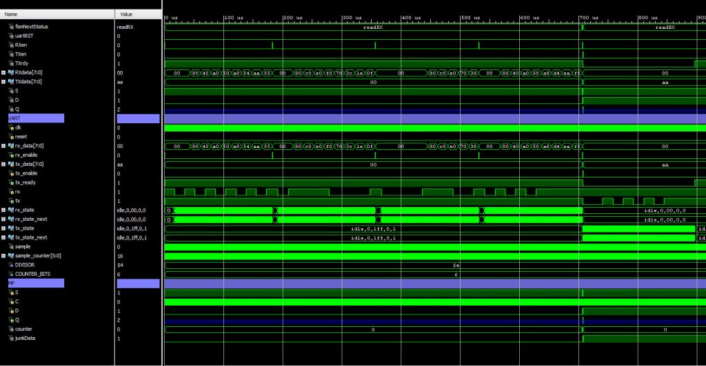
d) Projeyi bütün halinde test etmek için bir testbench yazarak XSIM ile benzetimini yapalım.
library IEEE;
use IEEE.STD_LOGIC_1164.ALL;

entity tb_FPGA is
--  Port ( );
end tb_FPGA;

architecture Behavioral of tb_FPGA is
component ZC0720FPGA is
    Port ( CLK : in STD_LOGIC;
           RX : in STD_LOGIC;
           TX : out STD_LOGIC);
end component;
constant period : time := 20ns; -- 50 MHz
signal CLK, RX, TX : STD_LOGIC;
begin
    FPGA: ZC0720FPGA
    port map(
        CLK => CLK,
        RX => RX,
        TX => TX);


    process begin
       CLK <= '0';
       wait for period/2;
       CLK <= '1';
       wait for period/2;
    end process;

    process begin
        RX <= '1';
        wait for 864*period;
        RX <= '0'; -- Start
        wait for 864*period;
        RX <= '1';
        wait for 864*period;
        RX <= '0';
        wait for 864*period;
        RX <= '1';
        wait for 864*period;
        RX <= '0';
        wait for 864*period;
        RX <= '1';
        wait for 864*period;
        RX <= '0';
        wait for 864*period;
        RX <= '1';
        wait for 864*period;
        RX <= '0';
        wait for 864*period;
        RX <= '1'; -- Stop
        wait for 864*period;
                RX <= '1';
                wait for 100*period;
                RX <= '0'; -- Start
                wait for 864*period;
                RX <= '1';
                wait for 864*period;
                RX <= '1';
                wait for 864*period;
                RX <= '1';
                wait for 864*period;
                RX <= '1';
                wait for 864*period;
                RX <= '0';
                wait for 864*period;
                RX <= '0';
                wait for 864*period;
                RX <= '0';
                wait for 864*period;
                RX <= '0';
                wait for 864*period;
                RX <= '1'; -- Stop
                wait for 864*period;
                                RX <= '1';
                                wait for 100*period;
                                RX <= '0'; -- Start
                                wait for 864*period;
                                RX <= '0';
                                wait for 864*period;
                                RX <= '0';
                                wait for 864*period;
                                RX <= '0';
                                wait for 864*period;
                                RX <= '1';
                                wait for 864*period;
                                RX <= '1';
                                wait for 864*period;
                                RX <= '1';
                                wait for 864*period;
                                RX <= '0';
                                wait for 864*period;
                                RX <= '0';
                                wait for 864*period;
                                RX <= '1'; -- Stop
                                wait for 864*period;
                                                RX <= '1';
                                                wait for 100*period;
                                                RX <= '0'; -- Start
                                                wait for 864*period;
                                                RX <= '1';
                                                wait for 864*period;
                                                RX <= '0';
                                                wait for 864*period;
                                                RX <= '1';
                                                wait for 864*period;
                                                RX <= '0';
                                                wait for 864*period;
                                                RX <= '1';
                                                wait for 864*period;
                                                RX <= '1';
                                                wait for 864*period;
                                                RX <= '1';
                                                wait for 864*period;
                                                RX <= '1';
                                                wait for 864*period;
                                                RX <= '1'; -- Stop
                                                wait for 864*period;
        RX <= '1';
        wait for 16*period;
        wait;
    end process;

end Behavioral;
Benzetim sonuçları